Blitz-wall Lightening Strike Protection for Pyranometers
Last update
Blitz-wall Lightening Strike Protection for Pyranometers
Blitz-Wall protects irradiance sensors, pyranometers and other photovoltaic monitoring systems from high-voltage surges caused by lightning during thunderstorms. It uses gas discharge technology and is IEC 61643-31 compliant.
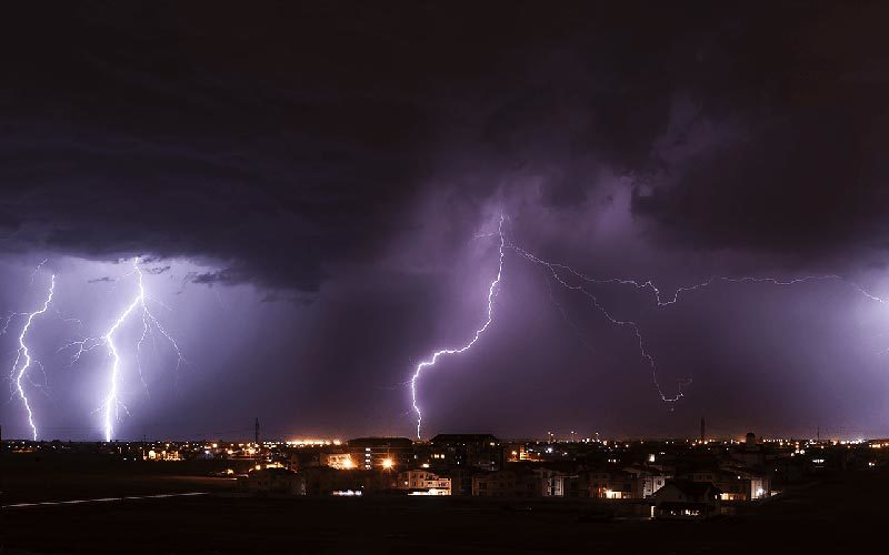
The recurring threat to large photovoltaic farms is no longer theft, but lightning strikes.
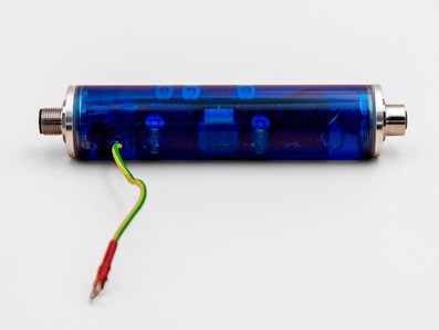
Blitz-Wall addresses a growing need to protect irradiance sensors and monitoring units of photovoltaic systems.
Blitz-Wall protects all types of sensors with 12 – 30 Vdc power supply from transient over-voltage induced by lightning.
It cleverly exploits gas discharger (GDT) technology, which are activated by conducting to the gorund the charge that has invested the system. The device is inside an acrylic polymer container, filled with UV-resistant resin.
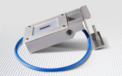
Blitz-Wall is conveniently inserted with plug and play connectors on the same cable that carries the power and signals between the data-logger and the sensor, in this case Sunmeter.
The advantages of Blitz-Wall
- Overvoltage protection during electric storms.
- Outdoor installation: unlike similar products on the market, Blitz-Wall is an IP66-rated device, so it can be installed outdoors near the sensor that is to be protected.
- Great value for money: unlike comparable products from well-known manufacturers, Blitz-Wall is half the price!
In addition to increasing the existing protection of the sensor, Blitz-Wall allows you to reduce extraordinary maintenance costs. In fact, when lightning strikes, the Blitz-wall intervenes and then self-restores within seconds. Should the discharge put Blitz-wall out of use, a replacement is less expensive both economically and in terms of technical time since you don’t have to wait around for a new sensor.
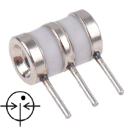
Blitz-Wall is based on gas discharge technology. Operation is guaranteed by the manufacturer for a finite number of discharge cycles to which it can be subjected. The number of discharges Blitz-Wall can take depends on the actual intensity of the lightening strikes.
How does Blitz-Wall protect photovoltaic systems from lightening strikes?
With two separate circuits, Blitz-Wall protects the power and data lines, for both analog and digital.
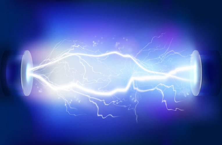
Blitz-Wall protection intervenes when transient over-voltages are produced by a lightning strike in the vicinity of a photovoltaic system. In such cases, important inductive phenomena occur along the cables close to the strike.
The gas dischargers are electrically coupled to inductors placed in series along the line for each protected line. Under normal conditions, the gas arrester is an open circuit and does not affect the line, because the potential difference across it (between the lines and the earth) is not sufficient to trigger the avalanche ionization of the gas inside the arrester, which therefore results in a high electrical resistance of the order of GOhm.
The inductor varies its impedance and therefore the voltage that falls across it as a function of the speed with which the signal passing through it varies over time. It is chosen so not to affect data communications with the typical transmission rates of the modbus system.
Depending on the intensity of the lightning, the type of coupling that induces the surge and distance from the strike: a lightning induced surge has a characteristic rise time that can reach 1-10 kV/us, followed by a voltage peak that can vary from 1-100 kV and then fade in a matter of milliseconds.
The rapid voltage variation in the rising phase of the discharge will “see” a high impedance across the inductor, which will prevent the passage of current, increasing the electrical potential across it and consequently across the voltage arrester of the line involved. Once the gas ionization threshold voltage in the arrester is exceeded, the gas becomes plasma and the electrical resistance suddenly collapses to a few tens of Ohms, closing the circuit between the line involved with the grounding and thus diverting the bulk of the energy.
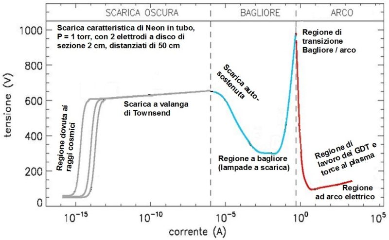
With the typical working currents of the arresters, they work in the region of the electric arc and the holding voltage of the plasma is lower than the activation voltage of the plasma itself in the arrester and this prevents the final tail of the discharge reaching the sensor (less intense but potentially dangerous). Once the discharge is complete, the voltage across the arrester will be lower than the plasma maintenance voltage, returning to the state of inert gas with a high electrical resistance and thus restoring the line involved.
Although Sunmeter is already protected from polarity inversion and over-voltage, this does not make Blitz-wall redundant, but rather makes it complementary. In fact, the Sunmeter’s protection exploits the technology of varistors which have an electrical operation similar to gas arresters but are based on completely different physical principles. The varistors intervene above 30V and protect against transient events within a maximum energy of a few Joules; whilst Blitz-Wall arresters are activated above 60V and manage maximum energy of several hundred Joules.
When lightening strikes, Blitz-wall absorbs the bulk of the energy. Any remaining energy is absorbed by the Sunmeter’s inbuilt protection.
Blitz-Wall has GDT arresters according to the redundancy principle. Consequently it will have a life expressed in quantity of cycles higher than that of the single trap. The table below shows the number of operations that each GDT discharger can perform, depending on the intensity of the discharge.
Operations that each gas discharger can undergo
| A/B* | Tension | Peak current | Operations |
|---|---|---|---|
| 8/20 | – | 10kA | 1 |
| 2/10 us | 6kV | 12kA | 10 |
| 8/20 us | 6kV | 500A | 150 |
* A/B are the parameters of a typical over-voltage waveform. A is the rising edge in us and B is the half-life in us..
Regulatory info
Power surge protection legislation for telecommunication systems is regulated by the IEC 61643-21: 2000 + Corrigendum 2001 and the EN 61643-21 standards, July 2001, integrated with EN 61643-21 / A2, January 2013.

